Export Terrain Contours from Blender Using Freestyle
Category
Last modified
16 February 2019
Introduction
Blender can be used to create contours from terrain and export them in a vector format (SVG). A vector file can be used to cut materials using a laser, CNC, or plasma cutter. It can also be post processed in programs like Inkscape to produce 2d art and maps. Blender does this by rendering using the Freestyle function.
Download Mt Taranaki.zip to use for this tutorial.
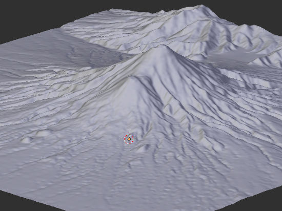
Mt Taranaki
Apply Modifiers and Extrude the Terrain
- Apply any modifiers applied to the model. If you have more than one then start from the top of the stack.

- RMB to select model.
- TAB into Edit mode.
- If no vertices are selected press A to select all.

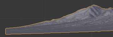
In Blender A toggles between select all and select none. - Press E to extrude and move the mouse down until the vertices are below the red line (0 on the Y axis)
- Press S, Z, 0, then ENTER
This scales the vertices on the Z axis by 0% to give the model a flat bottom. This is optional but useful if you want a flat base for 3d printing or cutting.
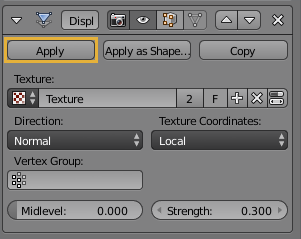
Apply displacement modifier.
Extruding the terrain.
Add Plane
- SHIFT A > M >> P
Add >> Mesh >> Plane. - S >> SHIFT Z >> 10000 >> ENTER
Add a plane and scale it so that it is larger than the terrain.
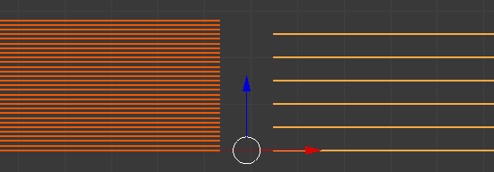
Add Array Modifier
- Add
 Array modifier.
  Uncheck Relative Offset.
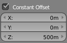
 Check Constant Offset.
- In the Z field type 100m (or your preferred contour distance).

- Increase the count to 30 (or the top of your terrain)
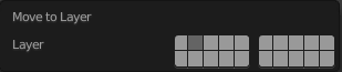
- M >> 2 >> ENTER
Move >> Layer 2
Add an Array modifier.
Add Boolean Modifier
- RMB select the terrain.
- Add
 Boolean modifier.
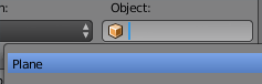
 - Choose the plane we created above.
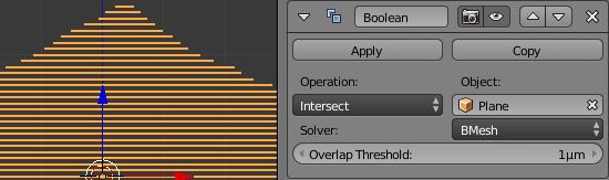
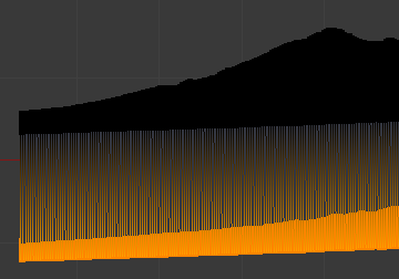
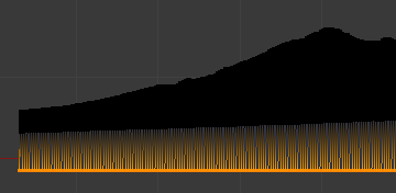
Boolean intersection of mountain and planes.
Use a  Boolean modifier to find the intersections between the planes and the mountain.
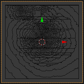
Add Camera
- Press Z to enter Wireframe mode.
- Press 7 on the numeric keypad to change to Top view.
- SHIFT A >> R to add a camera.

- Press 3 on the numeric keypad to change to Right view.
- LMB DRAG the camera above the terrain by the blue Z axis manipulator arrow.

Adding and positioning a camera.
Configure the Render Settings
- Click on
 in Properties.

- Change the resolution to square dimensions (or your preferred aspect ratio). 2000px x 2000px at 100%.

- Choose a location for exporting the SVG file.
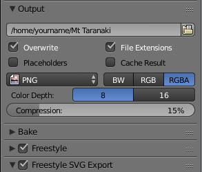
- Check
 and
and  .
.
Configure the Camera
- Click on
 in Properties.

- Change Lens type to Orthographic

- Changing the End clipping distance to 100km.

- Switch to Camera view by moving the mouse into the 3d Viewport and pressing 0 on the numeric keypad.
- Increase the Orthographic Scale until you see all of your model within the camera frame.

Export by Rendering
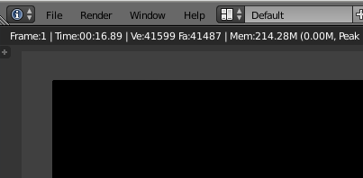
Press F12 to render. This will export the file to the path above.
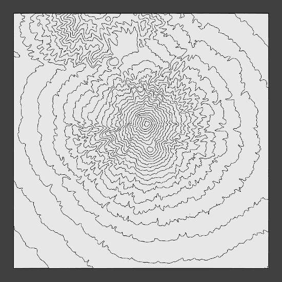
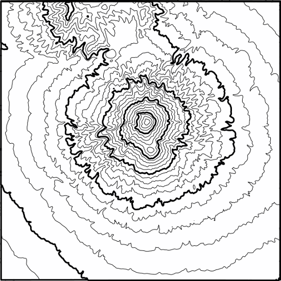
Mt Taranaki rendered as contours.
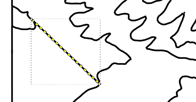
Troubleshooting
You may see some straight lines in odd places. These can be deleted in your vector graphics software, e.g. Inkscape:-
On export you may find some contours need to be closed:-
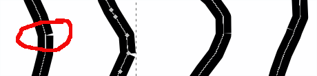
Converting 3d meshes to vectors is mathematically complex. You may get some joy in playing with the Freestyle settings. This is a known problem. In Inkscape:-
- Select all paths CTRL A
- Combine CTRL K them into a single object.
- Switch to Edit paths by nodes
 F2
F2 - CTRL A select all the nodes
- Join selected nodes SHIFT J.
If your computer grinds to a halt doing this then try again but select a smaller number of paths to combine and join in batches.
If you don't see anything on your screen when you render that may be because you have given your terrain any colour, not made it shadeless, nor placed lights. Open the exported file anyway and you will find that the lines are there.... they just didn't show in Blender because black lines on a black background are invisible.
Going Further
- If you want to have a thicker line after every so many contours then after the first render change the distance between contours.
- Change the line thickness in the Render settings

- Render to a new file and then combine them in your vector program.
Files
Discussion
16 September 2021
Mate! Awesome - have been trying to work out how to do something like this for ages. From a Kiwi to boot! Just need to learn Blender now...
Add a remark